


To reliably access the integrity of a material or the structures made of it, we need to know the geometry and size of flaws buried potentially inside the material. When ultrasonic waves are used for a nondestructive evaluation (NDE) of materials, therefore, an important goal is to reconstruct the shape of flaws from a set of ultrasonic echo signals.
To achieve this goal, a variety of ultrasonic imaging methods have been studied over the years. The synthetic aperture focusing technique (SAFT) is one of them. SAFT was originally developed for radar imaging applications and known also as a synthetic aperture radar (SAR). Like ultrasonic medical diagnoses, imaging is becoming a common practice in the field of industrial NDE as array ultrasonic transducers having tens of hundreds of transmitter/receiver elements and personal computers with a greater computational capability become more affordable. The former is indispensable for efficient and accurate ultrasonic echo measurements, while the latter is for the implementation of computationally intensive imaging algorithms.
SAFT – basic idea and algorithm
Algorithm
To understand how SAFT works, it suffices to look at the way it samples and converts ultrasonic echo amplitudes to an image intensity (pixel value) at a selected pixel. To this end, suppose that we’re inspecting a material transmitting ultrasonic beam from multiple locations. Suppose also that ultrasonic echoes coming back from the material are measured as a time-varying signal at multiple observation points. With the set of measured ultrasonic signals, the SAFT imaging goes as follows. For every ultrasonic signal, SAFT evaluates an ultrasonic time-of-flight (TOF) supposing that an ideal point scatterer is placed at the pixel point of interest. The echo amplitude at the estimated TOF is then picked up from the ultrasonic RF signal and assign it to the pixel as a partial image intensity. To obtain a complete image intensity, the echo amplitude associated with the pixel are collected from all available signals and are summed. In taking the sum, the amplitudes are often weighed so as to normalize the signals considering such factors as transmitter/receiver directivity and wave attenuation. By repeating the above operations for each pixel, SAFT synthesizes an image over a predefined grid of pixels.
Principle and Assumption
SAFT is based not on a rigorous wave theory. Rather it is based on the expectations that may be stated as follows. If a scattering source actually exists at the location of the pixel, ultrasonic echo signals should be summed coherently to give a pixel value of an appreciable level no matter how small each signal might be. If no scattering source exists there, potential echoes at the estimated TOFs are uncorrelated one another that their sum remains at a negligible level. If everything goes as expected, therefore, SAFT synthesizes an image in which scattering surfaces are highlighted. To see this, ultrasonic SAFT images of an irregularly shaped underwater object are shown in Fig.1. Good agreements are seen between the sample’s photos and the ultrasonic reconstructions. This is not an example of ultrasonic flaw characterization. However, the results clearly demonstrate that a simple SAFT can work well with measured signals and can reconstruct objects’ shape if condition permits.
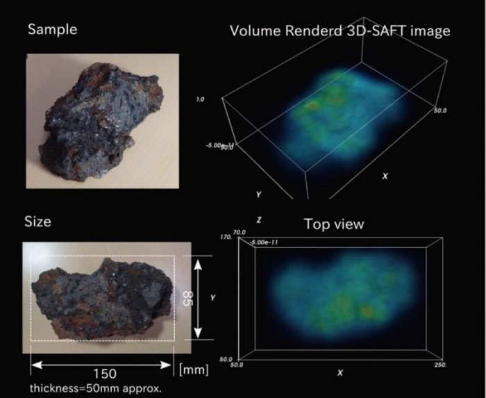
Fig.1: Volume rendered SAFT images of a porous and irregularly shaped underwater object as an example of successful 3D SAFT imaging of an extended object. To synthesize the image, ultrasonic waveforms were collected by a laboratory experiment in which imaging volume was scanned from above with a 1MHz ultrasonic transducer obtaining 787 echo signals. The author’s research group is developing an underwater SAFT system for objects having a complicated surface geometry. The potential application is the remote inspection of nuclear fuel debris formed in a reactor core of Fukushima Dai-ichi nuclear power plant. The fuel debris is believed to have a rough and irregular surface and could be porous.
SAFT has been used widely for ultrasonic reflector imaging due to its algorithmic and conceptual simplicity. It is the simplicity that makes SAFT a highly robust and close-to-real-time imaging method. However, the conceptual simplicity limits the method’s range of application sometimes severely. In a nutshell, the key operations of the SAFT algorithm are (1) TOF-based sampling and (2) weighed summation. In order for these operations to make sense, we have implicitly made two assumptions. The first assumption is that the points of transmission and reception can be defined without ambiguity. The second is that our measuring devices can record pulse-like waveforms. It is often further assumed that ultrasonic waves travel like a ray of light. Although this is not the requirement from the SAFT algorithm, the third assumption is made to reduce the TOF computation to a trivially simple ray tracing operation and thereby save computational cost hugely. If those assumptions are violated, ultrasonic signals are not mapped to a correct spatial location giving rise to significant artifacts and image blurring.
When does SAFT fail?
Unfortunately, there are many ultrasonic testing situations where one or more of the three assumptions fail. For example, the aperture width of conventional ultrasonic sensors is often many times larger than the wavelength. The aperture width is chosen to be so to transmit a narrow ultrasonic beam to the desired direction. Thus, we can not always determine the point of transmission precisely. Moreover, the temporal profile of the incident wave is usually oscillatory because the frequency bandwidth of ultrasonic sensors is limited. A frequency dependent reflectivity of scattering objects also deviates echo signals from a pulse-like temporal profile. Another thing that hampers a SAFT imaging is the mode conversion of ultrasonic waves. In a solid material, ultrasonic waves split into two or more modes (typically P- and S-wave) upon reflection and scattering. This means we have to trace multiple rays for the TOF computation. The worst thing about the emergence of multiple rays is that we cannot tell whether all those rays are equally important or only a small number of them dominate the measured signals without doing an involved wave field analyses. Obviously, such detailed analyses could compromise the simplicity and the efficiency of the imaging method.
Reverse Time-Migration Technique as a Highly General Imaging Method
Principle
In the field of geophysical exploration, a class of imaging method called reverse-time migration (RTM) has been used extensively to reconstruct earth’s interior structures from seismic survey data. In a seismic surveyed waveform, reflection waves coming from different depths are superimposed one another and recorded as a wave train. To identify the depth where a particular wavelet was coming from, RTM propagates (migrates) the recorded signal backward in time in a digitally simulated earth’s model. At the same time, the RTM simulates the evolution of the incident seismic waves forward in time on the same computer model. With the forward and reverse migrating fields, RTM identifies the source of reflection by looking for a location where the two fields meet. More precisely, RTM correlates the two fields with respect to time over an imaging volume to draw an intensity map of the reflection source. The type of correlation employed in the RTM imaging is called an “imaging condition”. A number of imaging conditions have been proposed to better reconstruct heterogeneous geological structures. Usually, RTM migrates wavefields forward and backward by solving the underlying wave equation numerically with such a method as finite difference or finite element. RTM is hence highly general in terms of wave source-receiver configuration, domain geometry, and the material properties through computationally intensive.
RTM vs SAFT
RTM and SAFT are somewhat different in their principle and the range of application. The former is a wave-equation-based migration approach that is computationally expensive but applicable to a broad range of problems. The latter is a simple easy-to-use, and computationally efficient method although applicable only to problems for which TOF be well-defined and amenable for quick numerical evaluations. RTM is used to explore spatially extended structures such as geological strata, while SAFT is primarily for the characterization of local heterogeneity such as cracks and voids embedded in an approximately homogeneous medium. Clearly, the two methods can be a good alternative when one method does not fit well to one’s imaging objective. However, it would be more beneficial from the viewpoint of practical ultrasonic NDE if we could design and use a hybrid of the two methods that inherits strong points of each method to the desired degree.
Time-Reversal Imaging Method for Ultrasonic NDE
Generalizing SAFT
Recently, the authors found that SAFT can be formulated as a special case of RTM. The key observation leading to this unification is to recognize that the sampling operation in SAFT can be regarded as cross-correlating the forward and the backward propagating fields assuming that the incident wave is an ideal Dirac’s delta pulse. Once the sampling operation is generalized as a cross-correlation, TOF computation becomes an option. In other words, the assumptions of the point transmitters and receivers are no longer needed in formulating SAFT. Another important finding is that the imaging condition that generalizes SAFT need not be found heuristically if the scattering surfaces to be inspected is free from mechanical stress. For that type of scatterers, the imaging condition is derived naturally from the stress-free boundary condition without making any assumption on the excitation of the scattered waves. This eliminates a major weak point in the formulation of SAFT, that is the point scatter assumption. Moreover, the new imaging condition furnishes a built-in mechanism for the estimation of the local orientation of the scattering surface, which has not been derived nor used with RTM or SAFT. Typical scattering objects having stress-free boundaries are cavities and open cracks. Those are the kinds of flaws that could seriously compromise the integrity of engineering materials. An imaging condition dedicated to this kind of scattering objects is therefore of a major interest in the context of ultrasonic NDE.
Exploring Potential of the New Time-reversal Imaging Method
In an author’s recent publication, the cross-correlation based SAFT with the new imaging condition is called elastodynamic computational time-reversal (CTR) method. Figure 2 shows an example of CTR reconstruction and a forward traveling wave field used for the reconstruction. The wave field structure, seen in the snapshot on the left, is highly complicated due to reflections at the domain boundary and the scattering by the embedded cavities. Despite the complication, the CTR has succeeded in identifying the small cavities by correctly focusing the associated wave field. CTR method was tested further in the publication with simulated scattered (ultrasonic) wave data.
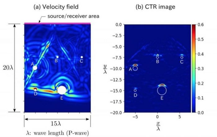
Fig.2: (a) A simulated elastic wavefield excited in a 2D domain containing five circular cavities A-E, and (b) the CTR reconstruction of the cavities. As shown in the snapshot (a), an angled longitudinal wave is excited on the source aperture indicated by a thick pink line. The incident field is reflected and scattered as it travels downward complicating the wave field structure significantly. The diameters of the cavities are 2λ for E, λ for A and λ/2 for B, C, and D where λ is the incident longitudinal wavelength. In (b), a CTR(computational time-reversal) image of the elastic medium is shown. The white circles indicate the locations of cavities A-E. Numerically simulated scattered waveforms for three different incident angles (0, +10 and -10 deg from the vertical direction) were used for the imaging. The CTR technique has focused the noisy wave field to the cavities, and thus top portions of the cavities have been identified successfully.
Specifically, cracks and voids of varying thickness are reconstructed from a set of simulated echo signals. It was found as the result that the CTR can accurately reconstruct an illuminated side of the scatterers resolving their radius of curvature down to the interrogating wavelength. It was thus shown that the CTR is capable not only of detecting small flaws but also of providing information on their geometry. Robustness of CTR was also demonstrated by reconstructing cracks in a plate. When elastic waves are excited in a plate, the waves reverberate undergoing mode conversions due to the repetitive reflection at the plate surfaces. This means the number of potential travel paths for the scattered waves increases so drastically that a TOF-based SAFT imaging can be prohibitively painstaking and inefficient. If CTR is implemented with the aid of a finite difference wave equation solver, the difficulties arising from TOF computations should be circumvented. As a result of our numerical tests, it was found that CTR can actually handle reverberating fields and detected the correct number of cracks at the correct locations. Moreover, the angle estimation mechanism built in the proposed imaging condition worked well that the crack orientation was captured correctly in the synthesized images. Although an experimental validation is yet to be made, it has thus been demonstrated that CTR works fairly well in ultrasonic testing situations that SAFT cannot cope with.
Implications
So far, the CTR has been implemented by solving the associated forward and reverse-time migration problems fully numerically. This is the reason why the method bears the name of “computational time-reversal”. Unfortunately, full numerical CTR is still computationally too expensive to be a practical method of ultrasonic imaging. It should be noted, however, that the forward and reverse-time migrating fields may be evaluated fully or partially by an analytical technique. Exact analytical solutions are rarely available for practical wave propagation problems. However, if we make some simplifying assumptions, closed-form analytical solutions can often be obtained. For example, ultrasonic wave fields excited by a circular PZT transducer has been studied in great detail. Numerous high-frequency, approximate, incident ultrasonic beam models for the circular transducers have been proposed as the result. If we use one of those models for a CTR imaging, we can gain computational efficiency at the expense of accuracy of the numerical wave fields used for the imaging. In fact, a classical SAFT was shown to be a kind of CTR in its simplest form. The implication is we can optimize CTR in terms of generality (weighed against the efficiency) by making a suitable degree of simplifying assumptions on the wave fields involved. Numerous ultrasonic measurement models reported in the literature would find many useful applications if used in this context.
Summary
RTM is a highly general and computationally intensive seismic imaging method that has been developed for geophysical explorations, while SAFT is a simple and computationally efficient algorithm that has been used for ultrasonic imaging of small scattering objects. The recent development of CTR (computational time-reversal method) intended for ultrasonic NDE of small flaws has established a link between the two classes of imaging methods. Numerical simulations have shown that CTR is a promising technique having a greater generality than the classical SAFT. To make CTR more practical, however, we have to enhance the computational efficiency probably by using analytical wave field solutions in some reasonable way. To make CTR more versatile, the imaging condition for general types of scattering objects needed to be found. In the course of making an effort in this direction, the authors believe that ultrasonic NDE researchers can learn a lot from geophysical exploration techniques. On the other hand, ultrasonic NDE techniques and practices might be found useful for those geophysicists who are trying to explore a highly localized object and to design a laboratory experiment to validate their method because those are the things that NDE engineers are doing every day. It would be great if future research and development related to CTR-like techniques help promote interaction between geophysicists and NDE engineers.
This study, An elastodynamic computational time-reversal method for shape reconstruction of traction-free scatterers was recently published in the journal Wave Motion.
Related Posts
 Improving Tools For Quality Improvement: Crossings, Runs, And Crossrun
 Coherent Poly Propagation Materials With 3-Dimensional Photonic Control Over Visible Light
 Reconstructing Commuter Networks Using Machine Learning And Urban Indicators
 Surprising Internal Structure Of Whole Wheat-Green Gram Functional Bread
 Tailoring Tomatoes To Match Individual Consumer Needs
 Eavesdropping On “Classroom Talk” In Undergraduate STEM Classrooms