


A CCL4 Lewis structure is a diagram that represents the electron configuration of covalently bonded compounds. Lewis structures are meant to provide a visualization of the atomic structure and the distribution of electrons in a given chemical compound.
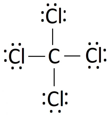
Carbon tetrachloride (CCl4) is a covalently bonded compound composed of a central carbon surrounded by 4 chlorine atoms in a tetrahedral structure. The Lewis diagram from carbon tetrachloride is:

A regular atom of carbon has 4 lone electrons in its outer shell. Chlorine has 7 electrons and so is 1 electron short of completely filling its outer shell. Thus, a carbon atom will share each of its 4 outer electrons with a single chlorine atom, giving the single carbon atoms and 4 chlorine atoms a full outer shell of electrons. in the resulting compound, each element has achieved a stable electron configuration by having 8 electrons in its outer shell.
“We define organic chemistry as the chemistry of carbon compounds.” — Augustus Kekule
Lewis Structures: The Basics
Lewis structures were first introduced by the American chemist G.N Lewis in 1916. Since then, they have become ubiquitous in high school and college level chemistry courses as an easy way to understand chemical bonding.
Lewis structures are meant to represent the atomic and electron structure of a chemical compound. Each element of the compound is represented in the Lewis structure by its chemical symbol, so H for hydrogen, C for carbon, O for oxygen, and so on. The configuration of the element’s electron shell is represented by a pattern of dots that surround the chemical symbol. Shared electron pairs are represented as a single line that connects the two bonded elements. Lone pairs of electrons (electrons that do not participate in chemical bonding) are represented as a pair of lone dots next to a chemical symbol.
How many dots are supposed to be around a symbol is determined by the element’s valence number—the number of electrons in its outer shell. Oxygen, for example, has a valence number of 6 because it has 6 electrons in its outer shell. Most elements will seek to fill their outer shell entirely and will bond with other elements until their valence number is 8, corresponding to a full outer shell of 8 electrons. The tendency for elements in compounds to arrange themselves to have a full valence shell of 8 electrons is called the octet rule. The lone exception to the octet rule is hydrogen. Hydrogen has a full outer shell with only 2 electrons and so will form bonds until it has 2 electrons.
“The only difference between elements and compounds consists in the supposed impossibility of proving the so-called elements to be compounds.” — Wolfgang Ostwald
So, for example, water (H2O) is a chemical compound composed of a single oxygen atom and two hydrogen atoms. Oxygen has 6 valence electrons, and hydrogen has 1 valence electron. Water is formed by an oxygen atom sharing each of its two lone electrons in the outer shell with a single lone electron in a hydrogen atom. Thus, water’s Lewis structure can be represented as:

The two solid lines connecting the hydrogen atoms to the oxygen atoms represent the shared pairs of electrons between them and the two pairs of lone dots represent the lone pairs of electrons in the oxygen atom. The valence number of hydrogen is 1 and the valence number of oxygen is 6, so adding those together gives us 1(2)+1(6)=8. So our diagram has 8 total electrons.
Rules For Making Lewis Structures
Lewis structures are an incredibly useful tool for figuring out the organization of a compound’s components. You can construct a Lewis diagram for a chemical compound by following these steps:
Step 1. Identify the total number of valence electrons in the diagram.
The total number of valence electrons in a Lewis diagram is equal to the sum of the valence numbers of the individual elements that compose the compound. Using CCl4 as our example, the total number of electrons in our diagram is equal to the sum of the valence number of carbon and the valence number for each atom of chlorine. Carbon has a valence number of 4 and each of the four chlorine atoms each have a valence number of 7. So the total number of electrons in our diagram of CCl4 should be:
1(4)+4(7) = 32 electrons.
Step 2. Sketch out a skeleton of the compound’s atomic structure.
Next up is to figure out the atomic organization of the compound. If the compound is diatomic (composed of only two atoms), then this is easy: the atomic structure will just be the two atoms sitting next to each other in a straight line. In a compound with three or more atoms, things get a bit more complicated. In most compounds with more than three atoms, there tends to be a central atom (or atoms) that shares bonds with multiple atoms. The central atom(s) tends to be the least electronegative element of the compound.
In our case, carbon is less electronegative than chlorine, so carbon is the central atom. We can sketch our diagram with a central carbon atom surrounded by 4 chlorine atoms, like this:

Step 3. Place a single bond between each bonded atom pair.
Now its time to fill in the diagram with electrons. Remember that a single line stands for one shared electron pair. Atoms form covalent compounds by sharing electrons, so every atom must share at least one pair of electrons with another atom. Adding a single bond to each atom in our previous diagram gives us:

Since each line counts for two electrons, we have used 8 electrons. That means we still have 32−8= 24 electrons left to place in the diagram.
Step 4. Starting with the outer atoms, fill in electron pairs until each outer atom satisfies the octet rule (except hydrogen, which gets 2).
Atoms seek to fill their outer shells with electrons, so they will attempt to do so before forming any other bonds. Fill in the diagram with electron pairs (dots) until every terminal atom is surrounded by 8 atoms. Remember that the shared atom pairs count towards the total number of valence electrons for each atom. Filling in our diagram gives us:

Since we just placed 12 electron pairs we have 24−12(2) = 0 electrons left to place. We placed them all!
Step 5. If any electron pairs remain, put them next to the central atom until it is full
Once the terminal atoms have a full octet, any extra electrons have nowhere else to go but back to the central atom. Place any leftover electron pairs around the central atom until the central atom has a full octet. These pairs will exist as lone pairs that remain unbonded.
In our case, we do not have any electrons leftover and every atom in our diagram satisfies the octet rule.
Step 6. If the central atom still does not have a full outer shell, move existing electron pairs together to form a double or triple bond.
If all the terminal atoms have a full shell, there are no more spare electron pairs to place, and the central atom still does not have a full outer shell, atoms have to get a bit creative. Existing electron pairs from the terminal atoms will move and join shared pairs of electrons to form double or triple bonds. A double bond is essentially the terminal atom and central atom sharing 4 electrons, 6 for triple bonds. Double bonds are represented with a double line (=) or a triple line (≡).
Following these steps, you can construct a Lewis diagram for a number of covalently bonded compounds. In our case, the final Lewis diagram for CCl4 is:
Limitations of Lewis Diagrams
Lewis diagrams are useful and accurate enough for determining the electron configuration of compounds composed out of main group elements, but they have some shortcomings. Not every chemical compound follows the exact bonding rules described above. As with any rule, there are exceptions. Transition metals, for instance, often don’t follow the octet rule and instead fill their outer shell with 12 electrons. For some compounds, there is no one adequate diagram, so the electron configuration of those compounds are described as a hybrid of multiple Lewis diagrams. These are called resonance structures.
“We are like an atomic structure. We’ve got a causal body that’s linked together.” — Frederick Lenz
Lewis diagrams also do not give much information regarding the 3-dimensional geometric orientation of the atoms, which is important for explaining the polarity and intermolecular bonding behavior of compounds. VESPR theory is a chemical modeling method that describes a molecule’s 3-dimensional shape and how that shape arises from the electrostatic repulsion of electron pairs. Electrons repel each other so a molecule tends to take a shape that minimizes the repulsion between electron pairs. This information can be used to predict the likely geometric structure of a given compound.
Additionally, Lewis diagrams do not explain why or how electrons form the bonds they do. That is a question that is left up to molecular orbital theory (MO theory), a mathematical technique that describes how electron orbitals combine in virtue of the wave-like properties of electrons.
In summation, Lewis diagrams are a useful and simple way to describe the electron configuration of covalently bonded compounds. A Lewis diagram can tell you how electrons are distributed in a compound and can be used to predict that distribution. Lewis diagrams are easy to construct and can be made by following a simple set of rules. Lewis structures of most compounds formed out of main group elements from periods 2–7 can be constructed by following the above ruleset.
Related Posts
 Be Careful When Speaking About Lead Pollution: The Good, The Bad, And The Ugly!
 Temperature Has A Significant Influence On The Production Of SMP-Based Dissolved Organic Nitrogen (DON) During Biological Processes
 Does The Arrow Of Time Apply To Quantum Systems?
 Labeled Periodic Table
 A “Twist” In Wavefunction With Ultrafast Vortex Electron Beams
 Chemical And Biological Characterization Spot The Faith Of Nanoparticles